You’re trying to drill into a stubborn metal piece with a stripped screw extractor bit, but your Ryobi drill press is spinning too fast—causing the bit to overheat and fail. Without the manual, you’re stuck wondering how to slow it down. Changing the speed on your Ryobi drill press doesn’t require complex tools or technical expertise—it’s a simple belt and pulley adjustment you can do in under five minutes. In this guide, you’ll learn the exact steps to safely adjust your Ryobi drill press speed for any material, from soft wood to hard metal, using the black plastic wing nut method that works on most models.
The key to mastering your Ryobi drill press lies in understanding its belt-driven speed system. Unlike variable-speed models, Ryobi uses fixed pulley positions to deliver specific RPM ranges. When your father-in-law used this drill press for copper pipe work, he likely ran it at higher speeds suitable for metal. But for delicate tasks like stripped screw removal, you need slower speeds to prevent bit damage and ensure clean cuts. By the end of this guide, you’ll confidently adjust speeds for any project and troubleshoot common belt issues that cause slipping or vibrations—no manual required.
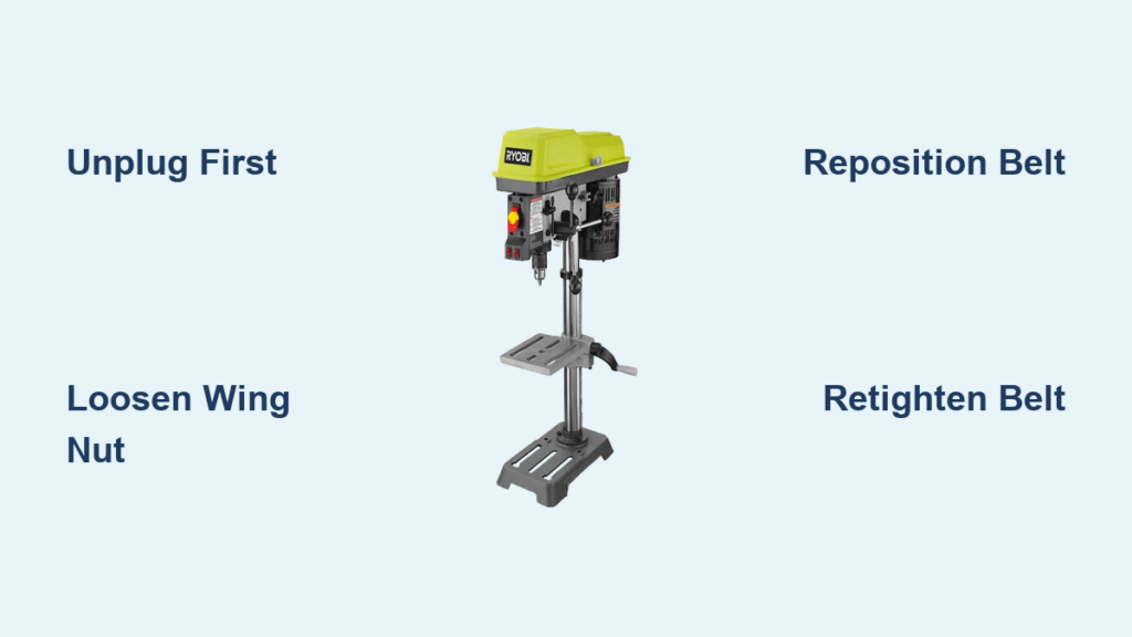
Unplug Your Ryobi Drill Press Before Any Speed Adjustment
Never skip this critical safety step. Your Ryobi drill press must be completely disconnected from power before touching any internal components. Locate the power cord and unplug it from the wall outlet—don’t rely solely on the power switch. This prevents accidental startup while your hands are near moving parts. Verify the machine is off by attempting to turn it on briefly (without inserting any bits). If you’re working in a shared workshop like your father-in-law’s, clearly mark the machine as “IN SERVICE” to prevent others from plugging it in during your adjustment.
Locate the Black Plastic Wing Nut Motor Mount on Your Ryobi Model
Your speed adjustment starts with finding the motor mounting mechanism. On most Ryobi drill presses, this is a large black plastic wing nut positioned on the left side of the machine near the motor housing. Crouch down and look between the motor and the column—you’ll see this distinctive nut holding the motor mount bracket. Some models may have two wing nuts (one on each side), but the left-side nut is your primary adjustment point. If you’re struggling to spot it, use a flashlight to illuminate the area—this is especially helpful if you’re working in a dimly lit workshop like the one your FIL used for copper pipe projects. The wing nut’s coarse threads allow for quick manual adjustments without tools.
Release Belt Tension by Loosening the Wing Nut (Step-by-Step)
How to Properly Loosen the Wing Nut Mechanism
Turn the black plastic wing nut counter-clockwise by hand until it’s loose but not fully removed. You’re not removing it—just creating enough slack to move the belt. As you loosen, gently push the motor forward toward the column. This pivoting action instantly releases tension on the drive belt. If your model has thumb screws on an S-shaped bracket instead, loosen those until the motor moves freely. Critical warning: Never force the motor—if it resists, check for additional locking mechanisms like setscrews hidden behind access panels.
Verify Adequate Slack for Belt Movement
With tension released, the belt should hang loosely between the motor and spindle pulleys. You need at least 1 inch of slack to reposition the belt easily. If the belt remains tight after loosening the wing nut, look for secondary tensioners like a setscrew on the motor bracket. Use a flathead screwdriver to gently pry the belt away from the pulleys while rotating the spindle by hand—this “hand-spin-and-pull method” creates just enough clearance to slide the belt into new positions.
Reposition the Drive Belt for Slower or Faster Speeds

Move the Belt to Lower Pulley Grooves for Slower Speeds
For stripped screw removal or metal drilling (like your FIL’s copper pipe work), you need reduced RPM. Slide the belt downward to the smallest groove on the motor pulley and the largest corresponding groove on the spindle pulley. This configuration creates maximum mechanical advantage for torque-intensive tasks. The speed chart sticker inside your belt guard (usually visible when the guard is open) shows exact positions—match the belt to the lowest RPM setting, typically labeled “500” or “750” for metal work.
Shift to Higher Pulley Positions for Wood and Plastics
When switching to softer materials, reverse the process: Position the belt on the largest motor pulley groove and smallest spindle pulley groove. This delivers faster spindle rotation ideal for small drill bits in wood or plastic. Never cross the belt between mismatched grooves—the chart ensures proper alignment to prevent premature wear. If your current setup spins too fast for screw extraction, you’re likely in the highest pulley position; dropping one groove combination often solves the problem.
Re-tension the Belt to Proper Tightness (1/4 Inch Deflection Rule)
Achieve Optimal Belt Tension Without Tools
After repositioning the belt, push the motor backward until the belt feels firm but not rigid. Apply moderate thumb pressure midway between pulleys—you should be able to deflect the belt vertically by exactly 1/4 to 1/2 inch. This “Goldilocks zone” prevents slippage during heavy drilling while avoiding bearing strain. If the belt squeals during operation, it’s too loose; if you detect burning smells or excessive heat, it’s dangerously over-tightened. Err on the looser side—you can always tighten incrementally after testing.
Lock the Motor Mount and Verify Belt Position
While maintaining tension, tighten the black plastic wing nut clockwise by hand until snug. Give the spindle a firm hand-spin to check belt tracking—stop immediately if you hear scraping or see the belt riding up on pulley flanges. Recheck tension after locking; the motor often shifts slightly during tightening. If vibrations occur during testing, slightly loosen the wing nut, reposition the belt fully into the groove, then re-tighten. This step is crucial for maintaining the precision your FIL relied on for pipe work.
Match Pulley Positions to Your Desired RPM Using the Speed Chart
:max_bytes(150000):strip_icc()/drill-press-chart-424bb9992cb84508936912ea46a0569f.jpg)
Decipher Your Drill Press’s Speed Chart Sticker
The sticker inside your belt guard (often yellowed with age in workshop settings) is your speed bible. It shows diagrams of all pulley combinations with corresponding RPM values. For stripped screw extraction, look for the slowest setting—typically 500-750 RPM. Match the belt position shown for that RPM: The top number indicates the motor pulley groove (count from the top down), while the bottom number shows the spindle pulley position. If the sticker is faded like many workshop relics, assume the lowest physical position equals slowest speed.
Troubleshoot Missing or Damaged Speed Charts
No visible sticker? Use this universal Ryobi rule: The belt position farthest from the motor creates the slowest speed. Start with the belt in the bottom groove on both pulleys for metal work. Test with a scrap piece—if the bit smokes, drop another groove; if it struggles to penetrate, move up one position. For copper pipe drilling (your FIL’s specialty), 1,000-1,500 RPM usually works; for stripped screw extraction, begin at 500 RPM and adjust upward only if absolutely necessary.
Test the New Speed Setting Safely (Without Chuck Key)
Conduct a Zero-Load Speed Verification
Before inserting any bit, plug in the drill press and run it for 10 seconds at the new setting. Stand clear of the chuck area and listen for abnormal noises. The motor should run smoothly without belt squeal or grinding. If vibrations occur, immediately unplug and recheck belt tension and seating. Critical reminder: Double-check that your chuck key is removed—this prevents dangerous projectile hazards during testing. Observe the belt’s movement; it should track straight without lateral wobble.
Validate Speed with Material-Specific Drilling
Grab scrap material matching your project (e.g., copper pipe for metal work). Insert a small bit and drill at light pressure. For metal: Chips should form clean “ribbons,” not dust (indicating excessive speed). For stripped screw extraction: The bit should bite cleanly without chattering. If the bit binds or overheats, stop immediately—you need slower speeds. Remember your FIL’s copper pipe work? He likely used higher speeds than you need for delicate extraction tasks.
Choose the Right Speed for Wood, Metal, or Masonry Drilling
Metal Drilling Speeds: Slow and Steady Wins
For copper, steel, or aluminum—including stripped screw extraction—always use the slowest practical speed. Start at 500 RPM for bits under 1/4″, increasing only if the bit won’t penetrate. High speeds overheat metal bits, causing blue discoloration and premature failure. Your FIL’s copper pipe work probably ran at 1,000-1,500 RPM; for hardened screw extractors, drop to half that speed. Apply cutting fluid generously at these slower speeds to dissipate heat.
Wood and Plastic: Match Speed to Bit Size
Small bits (under 1/4″) in wood/plastic need high speeds (2,500+ RPM) for clean cuts. Larger bits (1/2″+ Forstner/hole saws) require slower speeds (750-1,000 RPM) to prevent burning. Never drill wood at metal speeds—the heat will melt plastics or scorch wood. When switching from metal to wood projects, reset your belt position immediately; residual heat from improper speeds ruins bits faster than misuse.
Fix Common Belt Problems: Slipping, Squealing, or Vibrations
Stop Belt Slipping in 60 Seconds
If the motor spins but the chuck stalls during drilling, your belt is slipping. Unplug the press and increase tension by tightening the wing nut 1/4 turn. Retest—if slipping continues, check for glazed belt surfaces (shiny spots indicate wear). Clean with degreaser if dirty, but replace immediately if cracked. For emergency jobs, apply belt dressing spray sparingly to the underside, though this is a temporary fix.
Eliminate Squeals and Vibrations
Belt squeal means insufficient tension—tighten the wing nut incrementally while testing. Vibrations usually indicate misalignment: Ensure the belt sits fully in pulley grooves with no flange contact. If vibrations persist after repositioning, inspect for worn pulley bearings or a stretched belt. Replace belts showing fraying or >1/8″ width reduction—they’re inexpensive and critical for consistent speed control.
Extend Belt Life with Pro Maintenance Tips
Monthly Belt Checks That Prevent Downtime
After unplugging, spin the spindle by hand weekly to check for belt stiffness or cracks. Monthly, clean pulleys with a dry cloth to remove sawdust or metal shavings that cause slippage. Apply a light silicone spray to the belt’s non-contact side annually to prevent drying—never use oil-based lubricants. When storing the press, release belt tension slightly to avoid permanent stretching.
Create Your Custom Speed Reference Guide
Since manuals disappear like your FIL’s, mark ideal settings directly on the machine. Use a paint pen to note “STRIPPED SCREWS: POS 1” next to the slowest pulley position. Photograph the speed chart with your phone for quick reference. Keep a small notebook in the workshop recording successful settings for common tasks—this transforms guesswork into precision for future projects.
When to Replace Your Ryobi Drill Press Belt
Identify Critical Wear Indicators
Replace belts showing any of these signs: Glazed surfaces (prevents grip), cracks across the width, frayed edges, or >10% width reduction from original size. A failing belt causes inconsistent speeds that ruin drill bits—especially critical for delicate tasks like screw extraction. Measure your belt against a new one; Ryobi typically uses 8-10mm wide V-belts available at hardware stores for under $10.
Install New Belts Without Manual Guidance
After unplugging, fully loosen the wing nut and remove the old belt. Loop the new belt over both pulleys without forcing it into position. Re-tension gradually while rotating the spindle to seat the belt. Test at lowest speed first—new belts stretch slightly during initial use, requiring one re-tensioning after 30 minutes of operation. Keep the old belt as a backup; it often works for lower-torque wood projects.
Final Note: Mastering your Ryobi drill press speed adjustment unlocks professional results across materials—from your FIL’s copper pipe projects to delicate screw extraction. By following these belt-position methods, you’ll prevent bit damage, reduce workshop frustrations, and honor that inherited tool’s potential. Remember: Slow speeds for metal, high speeds for small wood bits, and always verify tension with the 1/4-inch deflection test. Keep this guide bookmarked for your next speed change—it’s the manual your workshop deserves.