When your drill suddenly loses power control or only works at full speed, the trigger switch is likely failing. Understanding drill trigger switch diagrams transforms confusing wiring into a clear repair roadmap. This guide explains exactly how to read these diagrams, diagnose problems, and safely replace your drill’s trigger switch using real-world examples from major brands like Black & Decker and Milwaukee. You’ll learn to identify common failure points and implement solutions that restore precise speed control.
A faulty trigger switch doesn’t just inconvenience you—it creates safety risks from unexpected tool activation to erratic operation. Whether you’re a DIY enthusiast or professional tradesperson, mastering drill trigger switch diagrams means extending your tool’s lifespan without costly service calls. This guide covers everything from basic wiring patterns to advanced circuit diagnostics.
Why Your Drill’s Trigger Switch Fails and How to Identify It
Drill trigger switches fail primarily due to electrical arcing across contacts, mechanical wear in the slider mechanism, or contamination of the variable resistor track. Spot these telltale signs before disassembling your tool:
- Intermittent power delivery where the drill cuts out during use
- Erratic speed control with sudden jumps or dead spots in trigger travel
- Burnt plastic smell or visible discoloration near the trigger housing
- Sticking trigger that doesn’t return smoothly to the off position
When testing with a multimeter, a healthy switch shows low resistance (less than 0.5Ω) across power terminals when fully pressed, with smooth resistance changes during partial activation. Never ignore a switch that feels gritty or makes crackling sounds—these indicate imminent failure that could damage your motor.
Common Failure Patterns by Drill Type
Cordless drills most often suffer from MOSFET failures in the speed control circuit, while corded models typically experience contact pitting from inductive loads. Hammer drills face additional stress from vibration, causing wire fatigue at terminal connections. If your drill works only in reverse mode, check the DPDT (Double Pole Double Throw) reversing switch connections first.
Essential Components of a Drill Trigger Switch System

Your drill’s trigger isn’t just an on/off button—it’s a sophisticated control system combining mechanical and electrical components. Understanding these parts helps interpret wiring diagrams:
- Dual-slider mechanism with one slider handling variable resistance (speed control) and another managing power contacts
- MOSFET circuit that amplifies small signals into motor-controlling power
- Forward/reverse selector that changes motor polarity through a DPDT switch
- Thermal protection components that prevent overheating damage
The variable resistor (potentiometer) works like a water valve—more trigger pull equals less resistance and more power to the motor. As you squeeze the trigger, a wiper moves along a resistive track, sending precise signals to the MOSFET that regulates power via Pulse Width Modulation (PWM).
Reading Standard Drill Trigger Switch Wiring Diagrams

Wiring diagrams use universal symbols that translate across brands. Learn these key elements to decode any drill trigger switch diagram:
- Solid lines indicate physical wire connections between terminals
- Dashed lines represent mechanical linkages (not wires)
- Triangle symbols denote MOSFET transistors in the control circuit
- Resistor symbols with arrows indicate variable resistors
Terminal markings follow standard conventions: L1/L2 for power input, COM for common connections, and LOAD for motor output terminals. If your diagram shows multiple numbered terminals (T1, T2, etc.), cross-reference with your specific model’s service manual for exact functions.
Black & Decker 3/8″ VSR Drill Wiring Explained
The Black & Decker 3/8″ VSR Drill (Model 7127) uses a Lucerne 5087 switch with a “two in, two out” configuration. The neutral line remains unswitched while the hot line passes through the trigger mechanism. When testing continuity:
- Measure 0 ohms between line and load pairs when trigger is pressed
- Verify smooth resistance changes across the variable resistor terminals
- Check reversing switch contacts show continuity in both directions
Critical mistake to avoid: Never assume terminal functions based on position alone—always verify with a multimeter since manufacturers vary terminal layouts.
Milwaukee Drill Trigger Switch Configuration Guide
Milwaukee drills (Part Numbers 58-01-1805 and 58-01-1806) feature more complex wiring due to electronic speed control. Their diagrams include:
- Power input terminals handling 18-20V from battery packs
- PWM control circuit connections to the variable resistor
- Motor output terminals with polarity reversal capability
- Thermal cutoff sensors wired in series with power lines
When replacing a Milwaukee switch, document the exact wire routing before disconnection. Their harnesses often include shrink-wrapped connectors that require careful handling. Pro tip: Photograph each connection point with a ruler in the frame to maintain scale reference during reassembly.
Step-by-Step: Testing Your Drill Trigger Switch with a Multimeter

Before ordering replacement parts, confirm the switch is faulty with this diagnostic process:
- Disconnect all power sources—remove battery packs and unplug corded models
- Set multimeter to continuity mode (or 200Ω resistance range)
- Test main power terminals: Place probes on input and output terminals
- Should show open circuit (O.L.) when trigger released
- Should show near 0Ω when fully pressed
- Check variable resistor: Measure resistance while slowly pulling trigger
- Should show smooth, continuous change from high to low resistance
- Jumps or dead spots indicate track wear
Warning: If you measure infinite resistance when the trigger is fully pressed, the switch has failed open and needs replacement. If resistance drops erratically, clean the resistor track with electronics contact cleaner before considering replacement.
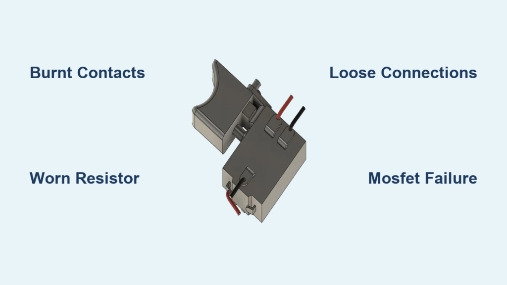
Common Trigger Switch Wiring Problems and Solutions
Intermittent operation typically stems from one of three issues visible in wiring diagrams:
- Burnt contacts showing high resistance (>1Ω) under load—replace the entire switch assembly
- Worn resistor tracks causing erratic resistance changes—clean with contact cleaner or replace
- Loose terminal connections creating voltage drops—re-terminate wires with proper crimps
The troubleshooting matrix below helps match symptoms to solutions:
| Symptom | Likely Cause | Solution |
|---|---|---|
| Drill works only at full speed | Failed MOSFET bypass circuit | Replace entire switch assembly |
| Trigger sticks in mid-position | Mechanical binding in slider | Lubricate pivot points with dielectric grease |
| No power in reverse mode | DPDT switch contact failure | Clean or replace reversing mechanism |
Critical insight: If your drill works only when you wiggle the trigger, you have a broken internal connection—this requires switch replacement, not repair.
How to Replace a Faulty Drill Trigger Switch Safely
Replacing a trigger switch requires meticulous attention to wiring details. Follow this sequence:
- Document existing wiring with clear photos from multiple angles
- Remove one wire at a time, immediately connecting it to the matching terminal on the new switch
- Verify terminal compatibility—new switches may have different markings but identical functions
- Test before final assembly—reconnect battery and verify operation without housing
Never skip the thermal test: Run the drill at 50% and 100% throttle for 30 seconds each, then check for abnormal heating at connections. Excessive warmth indicates improper terminal connections or undersized replacement parts.
Preventing Future Trigger Switch Failures: Maintenance Tips
Extend your trigger switch lifespan with these proactive measures:
- Clean resistor tracks quarterly using electronics contact cleaner and non-linting swabs
- Lubricate mechanical pivots with dielectric grease during annual maintenance
- Avoid full-throttle starts—gradually increase speed to reduce contact arcing
- Store drills in dry environments to prevent moisture-related corrosion
Professional tradespeople should implement a monthly maintenance schedule: visually inspect switches for damage, measure contact resistance, and verify smooth trigger operation. Key warning: If contact resistance exceeds 0.5Ω during testing, replace the switch immediately—delaying invites catastrophic failure.
Understanding drill trigger switch diagrams transforms intimidating repairs into manageable tasks. By recognizing standard wiring patterns and failure symptoms, you’ll diagnose problems faster and perform reliable repairs. Always prioritize safety by disconnecting power sources before working on electrical components, and when in doubt, consult your tool’s service manual for model-specific diagrams. With proper maintenance, a quality replacement switch should deliver 1,000,000+ reliable trigger cycles—getting you back to work with precise speed control.