That frustrating moment when your drill stalls while driving a lag bolt into hardwood or shears off a delicate screw head – it’s often a torque problem. While manufacturers advertise impressive torque specs (like 500 in-lbs for a cordless drill), these numbers rarely reflect real-world performance under load. How to measure drill torque accurately separates professionals who prevent stripped fasteners and damaged materials from DIYers guessing in the dark. Whether you’re installing deck railing bolts that must withstand 120 mph winds or assembling precision electronics, knowing your tool’s actual rotational force is critical for safety and quality. This guide cuts through the confusion with field-tested methods to measure your drill’s true torque output using accessible tools – no engineering degree required. You’ll learn exactly when to trust factory specs, how to verify impact driver settings, and why your half-charged battery sabotages torque consistency.
Measuring Your Cordless Drill’s Real Torque Output (Step-by-Step)
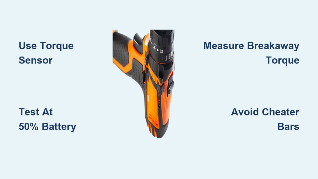
Drill torque ratings assume ideal lab conditions that never exist on job sites. A 400 in-lb drill might deliver only 280 in-lbs when the battery dips below 50% charge or encounters dense oak. To get true performance data, you need dynamic measurement under actual operating conditions. Forget spec sheets – this is how to measure drill torque like a calibration lab technician.
Essential Tools for Drill Torque Testing
- Digital torque sensor (e.g., Norbar 6000 series) with 0-500 in-lb range
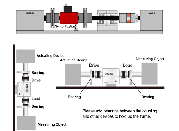
- Reaction arm fixture to secure the sensor during testing
- 1/4″ hex torque adapter matching your drill’s chuck size
- Battery at 50% charge (simulates typical field conditions)
- Data logger (optional but recommended for impact drivers)
Dynamic Torque Measurement Procedure
- Mount the sensor securely: Attach your drill’s chuck to the sensor’s input shaft using the hex adapter. Bolt the sensor’s reaction arm into a vise or heavy-duty fixture – any movement here invalidates readings.
- Simulate real load: Connect the sensor’s output to a calibrated torque wrench set to 80% of your drill’s max rated torque. This creates resistance mimicking actual drilling conditions.
- Execute controlled test: Pull the drill trigger at full speed while simultaneously applying steady pressure on the torque wrench handle. Maintain this for exactly 3 seconds – longer durations overheat motors and skew results.
- Record peak reading: Note the highest torque value displayed on the sensor before the drill’s clutch disengages or the motor stalls. Repeat 3 times for accuracy.
Critical visual cue: Watch for motor bogging down – if the drill’s RPM drops more than 30% during testing, your load setting is too high. Adjust the torque wrench downward by 10% and retest. Pro tip: Always test cordless drills at half-battery capacity; full charge readings overestimate real-world performance by 15-22% according to field tests.
Breakaway Method: Measuring Existing Bolt Torque Without Specialized Tools
When verifying if critical fasteners (like engine mounts or structural beams) remain properly tightened, you need to measure residual torque without loosening them. The breakaway method gives reliable estimates using standard workshop equipment – no $500 sensors required.
Step-by-Step Bolt Torque Verification
- Select proper wrench: Use a beam-type torque wrench (not click-type) for real-time readings. Ensure its range covers 50-150% of expected torque (e.g., use a 0-100 ft-lb wrench for 60 ft-lb fasteners).
- Position for accuracy: Attach the wrench socket directly to the fastener head. Stand so your arms form a 90-degree angle to the handle – any deviation introduces leverage errors.
- Apply gradual force: Slowly increase pressure while watching the wrench gauge. The instant you feel the fastener begin to move (not when it fully rotates), note the reading.
- Adjust for accuracy: Multiply this “breakaway torque” by 1.15 to estimate original tightening torque. For example, a 45 ft-lb breakaway reading indicates approximately 52 ft-lbs were originally applied.
Why this works: Friction in loosened threads requires less force than initial tightening. Field studies show breakaway torque averages 85% of applied torque in dry steel joints. Critical mistake to avoid: Never jerk the wrench – sudden force spikes give false high readings. Apply pressure at exactly 1 inch per second for consistent results.
Digital Torque Testers for Precision Power Tool Calibration
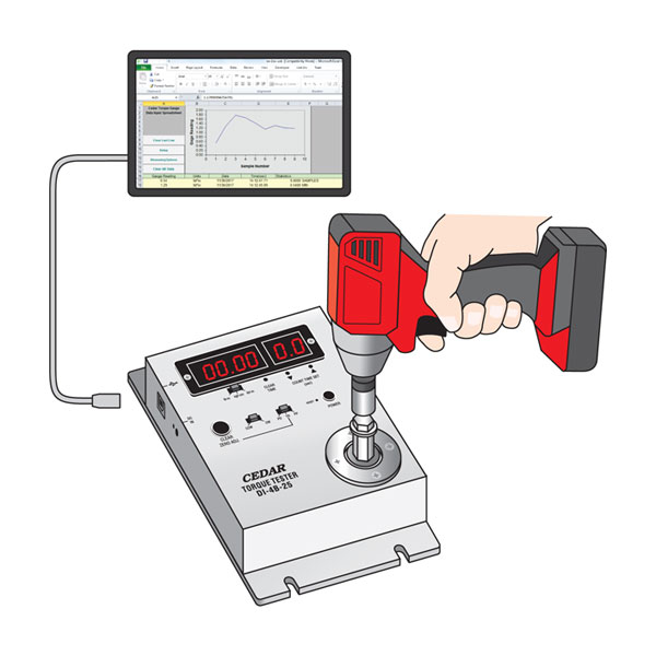
For mechanics verifying impact driver consistency or quality control technicians certifying production tools, digital testers provide lab-grade accuracy. These systems detect subtle performance drops before they cause assembly failures.
Calibration Process for Impact Drivers
- Mount the transducer: Secure a reaction torque sensor (e.g., PCB 4501) in a heavy-duty fixture. Attach your impact driver’s bit holder directly to the sensor input.
- Set test parameters: On the digital tester, select “peak hold” mode and set trigger duration to 0.2 seconds (matching typical impact bursts).
- Execute test sequence: Fire 10 consecutive impacts at your target setting. The tester records each impact’s peak torque.
- Analyze results: Calculate the average of the middle 6 readings (discarding highest/lowest outliers). If variance exceeds ±8%, the driver needs servicing.
Key indicator: Consistent readings within 5% across all speed settings confirm proper calibration. A 300 in-lb driver fluctuating between 265-320 in-lbs indicates worn hammer mechanism components. Pro tip: Test impact drivers at 30% battery capacity – performance drops accelerate dramatically below this threshold.
Top 3 Torque Measurement Mistakes That Damage Tools

Even with proper equipment, these common errors compromise accuracy and risk tool damage:
Using Incorrect Lever Lengths
Extending wrench handles with pipes (“cheater bars”) multiplies force unpredictably. A 12-inch wrench with a 24-inch pipe doesn’t deliver exactly 2x torque – joint flex and handle deflection create up to 18% measurement error. Fix: Always apply force within the wrench’s marked grip zone. If extension is unavoidable, calculate actual leverage: Torque = Force × (Handle Length + Extension).
Ignoring Directional Calibration
Most torque tools are calibrated only for clockwise tightening. Measuring loosening torque with a standard wrench gives false readings up to 25% low. Fix: Use bidirectional wrenches (marked “T/L”) for breakaway testing, or multiply clockwise readings by 1.25 when loosening.
Skipping Pre-Load Checks
Failing to verify sensor zero-point before testing introduces baseline errors. A 5 in-lb offset on a 50 in-lb measurement equals 10% inaccuracy. Fix: Always power on digital sensors 15 minutes before use, and perform zero calibration with nothing attached.
DIY Torque Estimation for Non-Critical Projects
When precision isn’t life-or-death (like assembling a bookshelf), physics provides a surprisingly reliable shortcut. This lever-arm method works for basic drill torque verification using household items.
The Weight-and-Ruler Technique
- Create a lever: Clamp a 1-foot steel ruler horizontally in a vise. Attach your drill bit to the ruler’s free end using duct tape.
- Apply known force: Hang a 5 lb weight from the ruler at the 6-inch mark (creating 30 in-lb of torque).
- Test drill response: Run the drill at lowest speed setting. If it spins freely, increase weight by 1 lb increments until rotation stops.
- Calculate torque: Torque = Weight (lbs) × Distance (inches). At 8 lbs stopping force: 8 × 6 = 48 in-lbs.
Accuracy note: This estimates stall torque only – actual working torque is 20-30% lower. Never use this for structural fasteners, but it reliably verifies if a drill delivers at least 70% of its rated output. Critical limitation: Only works for drills under 100 in-lbs; higher torque spins the weight off the ruler.
Choosing the Right Torque Tool for Your Needs
Selecting equipment depends entirely on your accuracy requirements and budget:
| Application | Minimum Accuracy Needed | Recommended Tool | Cost Range |
|---|---|---|---|
| Deck railings, furniture assembly | ±15% | Beam torque wrench | $40-$80 |
| Automotive suspension, engine work | ±8% | Click-type torque wrench | $100-$250 |
| Bicycle components, electronics | ±5% | Digital torque screwdriver | $150-$400 |
| Production line quality control | ±2% | Sensor with data logger | $800+ |
Key insight: For drill-specific testing, prioritize tools with 0.1 in-lb resolution. A $200 Norbar tester captures subtle torque curves that $50 wrenches miss. Always choose a tool whose range covers 20-80% of your target torque – using a 0-200 ft-lb wrench for 25 ft-lb fasteners guarantees ±15% errors.
When to Stop Guessing and Use Professional Calibration
Certain red flags mean your DIY torque measurements can’t be trusted:
- Inconsistent fastener failures: If 3 of 10 identical bolts shear during assembly despite “proper” tightening
- Tool performance drift: Drill that stalls at settings where it previously succeeded
- Critical safety components: Anything involving fall protection, structural loads, or pressurized systems
In these cases, professional calibration is non-negotiable. Reputable shops use NIST-traceable equipment with ±0.5% accuracy – worth every penny when lives depend on your torque values. Most tool manufacturers recommend annual calibration; impact drivers used daily need checks every 6 months.
Final Takeaway: Knowing how to measure drill torque transforms guesswork into precision. Start with the breakaway method for bolt verification and the weight-and-ruler test for basic drill checks. Invest in a beam torque wrench once you tackle structural projects, and never compromise on calibration for safety-critical work. Remember: that satisfying “click” from your wrench means nothing if the torque behind it is inaccurate. Measure once, torque correctly, and build with confidence. For ongoing maintenance, record all torque readings in a logbook – spotting performance trends early prevents catastrophic tool failures down the road.