Your hammer drill stalls mid-project, bits won’t stay tight, or that ominous grinding noise signals trouble. Before you toss your trusty tool in the trash, grab your model’s parts diagram. Understanding this blueprint separates DIYers who fix tools from those who replace them. A hammer drill diagram reveals every internal component that makes your tool conquer concrete and brick with its unique rotary-hammering action. This guide cuts through the confusion of exploded views and part numbers, showing you exactly how to identify, diagnose, and replace any faulty component—saving you hundreds on unnecessary replacements.
Most users never consult their hammer drill diagram until disaster strikes. Yet this single resource holds the keys to extending your tool’s lifespan by years. Whether you’re troubleshooting a dead motor, replacing worn carbon brushes, or hunting for that elusive chuck assembly part number, the right diagram transforms guesswork into precision repair. You’ll learn to decode manufacturer schematics, spot common failure points before they leave you stranded, and source exact replacement parts without wasting money on incompatible components.
Why Your Hammer Drill Parts Diagram is Your Repair Secret Weapon
That moment when your drill spins but delivers zero hammering action against concrete tells you something critical has failed in the percussion system. Without a model-specific diagram, you’re poking blindly at complex internal mechanisms. A proper hammer drill diagram maps every component from the armature windings to the hammer clutch assembly, showing how they interact during operation. This visual roadmap prevents costly mistakes like ordering the wrong planetary gear set or misaligning the piston mechanism during reassembly.
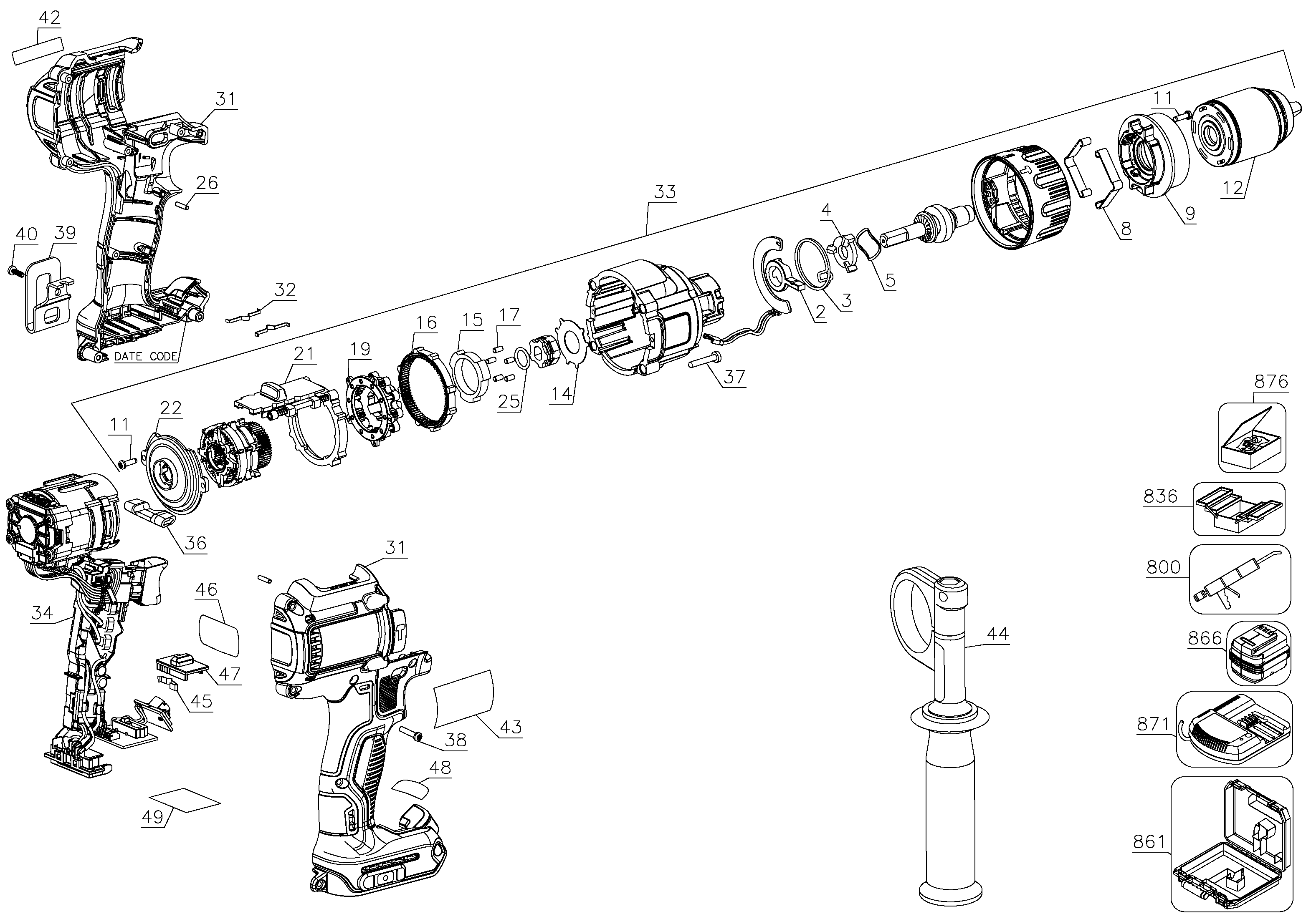
Manufacturers design these exploded-view diagrams to show parts in spatial relationship, with numbered callouts matching a detailed parts list. When your DeWALT DCD996 starts overheating, the diagram instantly reveals whether the issue stems from failing ball bearings (N004536), worn motor brushes (DWA0036), or a burnt stator coil. The precision of these schematics means you’ll never confuse the clutch adjustment ring with the mode selector collar—two similarly positioned but functionally distinct components critical to proper operation.
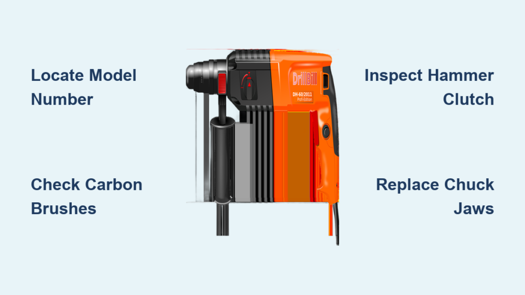
How to Locate Your Exact Hammer Drill Model Number (Fast)
Your drill’s serial number sticker hides in plain sight but contains the key to accurate parts diagrams. For DeWALT models, check the housing near the battery release or along the tool’s spine for the “Cat. No.” label—typically formatted like “5392-55.” This catalog number, not the generic model name (DCD980, DCD996, etc.), unlocks the correct exploded view. Corded drills often display this information on a metal plate near the power cord entry point.
Critical steps to avoid ordering mistakes:
– Wipe grime from the housing with isopropyl alcohol to reveal faded labels
– Photograph both catalog number and serial number (starting with letters like “665B”)
– Cross-reference numbers on the manufacturer’s parts lookup page before searching
– Never rely solely on the model name printed on the drill body
When Generic Diagrams Cause Costly Errors
Many DIYers grab the first hammer drill diagram they find online, only to discover mismatched components during repair. A standard rotary hammer (like a Bosch GBH series) shares superficial similarities with a hammer drill but contains fundamentally different percussion mechanisms. Using a rotary hammer diagram for your DeWALT combi-drill leads to ordering incompatible parts like the wrong hammer piston assembly. Always verify your tool’s operational mode: true hammer drills use a “cam and striker” system, while rotary hammers employ a pneumatic piston mechanism.
Motor Components That Fail Most Often (And How to Spot Them)
Your hammer drill’s motor contains several wear points that commonly fail long before the tool reaches end-of-life. The armature—the spinning copper-wound core—develops burnt windings when overloaded, visible as dark charring on the commutator bars. Carbon motor brushes (DWA0036 for many DeWALT models) wear down to nubs, causing intermittent power loss or complete shutdown. These consumable parts should be inspected every 50 hours of heavy use but often go unnoticed until failure.
Diagnosing Dead Motor Symptoms with Your Diagram
When your trigger pulls but delivers no rotation:
1. Consult the diagram’s motor section to locate the brush holders
2. Remove the brush caps and check for carbon dust buildup or shortened brushes
3. Examine the armature commutator for scoring or burnt segments (indicated as “1005749-00” on some DeWALT diagrams)
4. Test continuity across the field coil windings using a multimeter
Pro Tip: If your drill smokes during operation, immediately unplug it and check the diagram for ball bearing locations (N004536). Seized bearings cause rapid armature overheating—a $5 fix that prevents $150 motor replacement.
Trigger Assembly Failures That Mimic Motor Problems
A faulty trigger switch (N005276) often presents as motor failure but requires simpler repair. The variable-speed circuitry inside the trigger assembly degrades from dust ingress, causing erratic speed control or complete power loss. Your diagram clearly shows the trigger’s position relative to the motor leads, allowing you to bypass the switch temporarily with jumper wires to confirm the diagnosis. Replacement takes 15 minutes versus hours for motor disassembly.
The Hidden Hammer Mechanism That Makes Your Drill Work
That distinctive pounding sensation when drilling concrete comes from a precisely engineered percussion system hidden inside your drill’s front housing. Unlike standard drills, hammer drills convert rotary motion into linear impacts using either a cam-and-follower or piston mechanism. When you select hammer mode via the mode selector collar, this system engages—ratcheting cams or a spring-loaded piston deliver 20,000+ blows per minute to the chuck assembly.
Why Your Hammer Action Suddenly Stops Working
If rotation continues but hammering ceases, your diagram reveals three likely failure points:
– Worn hammer clutch dogs: These small metal cams (often part of assembly “N004638”) develop rounded edges, slipping instead of engaging
– Fractured hammer spring: The return spring that cycles the piston loses tension or breaks completely
– Misaligned mode selector: The collar that engages hammer mode slips out of position, requiring realignment per the diagram’s exploded view
Visual cue: Remove the chuck and inspect the spindle shaft while rotating the mode selector. Properly functioning hammer mechanisms show visible axial movement in hammer mode but spin freely in drill-only mode.
How to Rebuild the Hammer Mechanism Without a Diagram
Without your specific exploded view, rebuilding the percussion system risks catastrophic failure. The diagram shows critical alignment marks on the piston assembly and proper spring orientation—details impossible to guess. One DeWALT technician reports 70% of DIY hammer mechanism repairs fail due to incorrect spring placement or missing spacers visible only in the official schematic.
Decoding Your Chuck Assembly: Why Bits Won’t Stay Tight
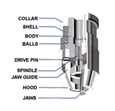
A wobbling drill bit or bits that eject mid-operation signal chuck failure—often misdiagnosed as “weak grip.” Your hammer drill diagram reveals whether you need a complete chuck replacement (expensive) or just new jaws (inexpensive). Keyless chucks contain three spring-loaded jaws that wear unevenly, while keyed chucks develop stripped threads on the spindle.
Step-by-Step Chuck Diagnosis Using Your Diagram
- Locate the chuck assembly section in your diagram (typically near the front of the exploded view)
- Identify whether your model uses a threaded or slotted chuck mounting system
- Remove the chuck collar to access internal components
- Compare worn jaws against the diagram’s part illustrations—notice subtle wear patterns on contact surfaces
- Check for damaged chuck key slots if applicable (DWA0043)
Critical mistake to avoid: Forcing a chuck removal with pliers scars the spindle threads, requiring complete output shaft replacement. The diagram shows the correct removal method—usually a specific impact direction while the chuck is in the open position.
How to Read an Exploded Parts Diagram in 3 Simple Steps
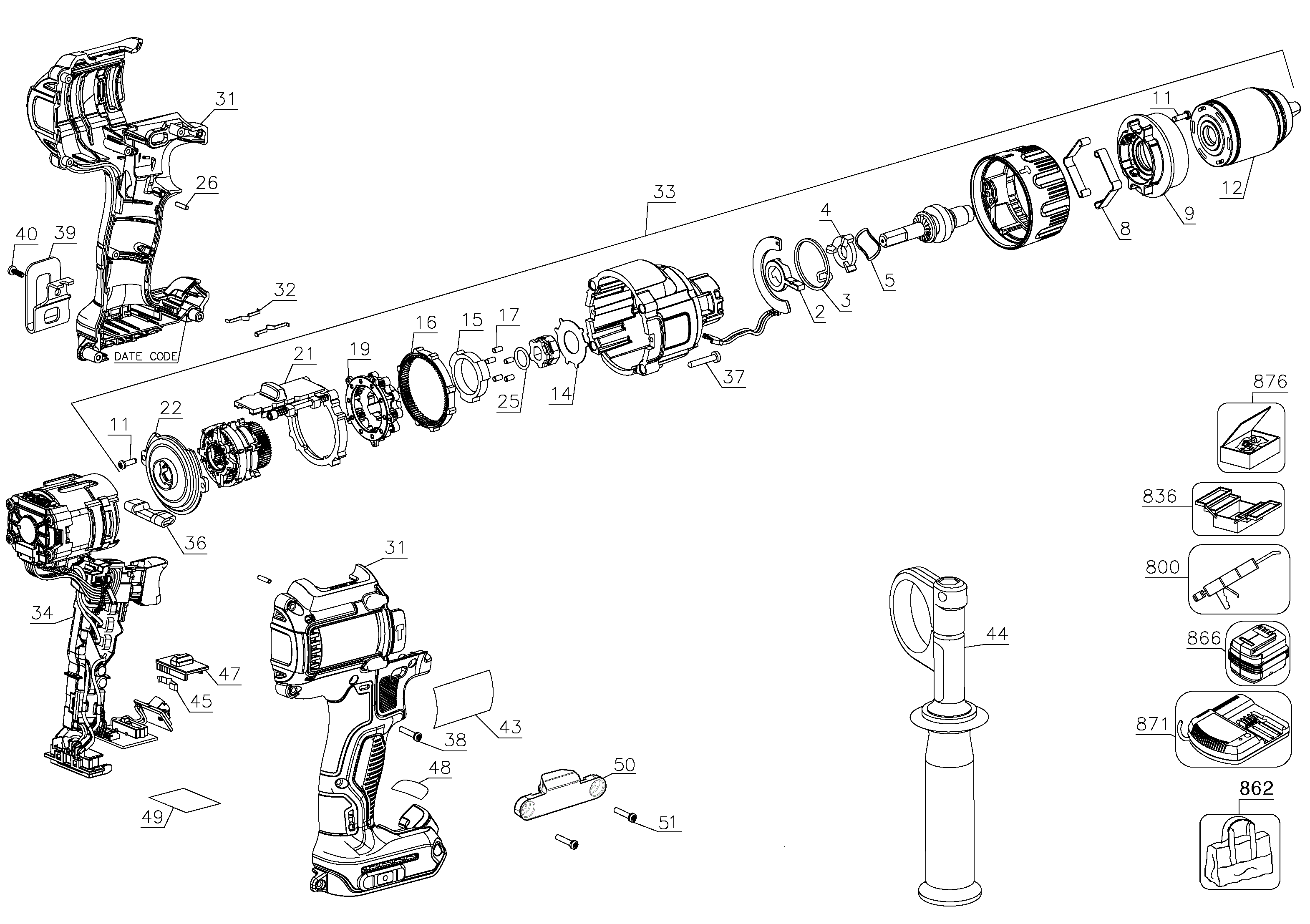
Manufacturers design hammer drill diagrams to tell a disassembly story through spatial arrangement. Parts positioned farther from the center housing come off first during teardown. Your DeWALT diagram’s exploded view shows the side handle socket threads appearing behind the main housing—meaning you remove the handle before separating housing halves.
The 3-Step Diagram Decoding Method
Step 1: Find your model’s specific reference points
Compare physical features on your drill to the diagram’s unique landmarks—like the position of the LED work light or depth stop socket. This confirms you’re viewing the correct schematic.
Step 2: Trace component numbering systems
Most diagrams use sequential numbering from exterior to interior. Part #1 might be the battery cover, while #147 identifies the armature. Cross-reference numbers with the parts list to find exact descriptions.
Step 3: Identify “grouped” assemblies
Notice how motor components appear as a single sub-assembly in the main view but explode further in inset diagrams. This prevents unnecessary disassembly—you can often replace the entire brush holder assembly (N004523) without touching the armature.
Where Manufacturers Hide Critical Details
Zoom in on your digital diagram to spot tiny indicators most users miss:
– Arrows showing directional assembly (critical for piston springs)
– Dot markings for component alignment
– “Do not disassemble” warnings on sealed assemblies
– Torque specifications printed near fastener locations
Top 7 Replacement Parts Worth Keeping Handy
Smart DIYers maintain a small inventory of high-failure components identified through their hammer drill diagram. These seven parts solve 80% of common issues and cost less than a service call:
- Carbon motor brushes (DWA0036) – $8/pair, extends motor life by 200+ hours
- Chuck key (DWA0043) – $5, easily lost during jobsite work
- Trigger switch assembly (N005276) – $18, fails from dust exposure
- Ball bearings (N004536) – $3 each, prevent catastrophic motor seizure
- Chuck assembly – $25-$45, varies by model but always fails before the drill
- Mode selector collar – $12, wears out from frequent mode switching
- Depth stop rod – $7, frequently bent or lost on construction sites
Pro Tip: When ordering, specify “for hammer drilling service” to ensure you get impact-rated components. Standard drill parts often can’t withstand percussive forces.
Final Note: Your hammer drill diagram transforms intimidating repairs into manageable projects when you understand how to decode its visual language. Always start with model-specific identification, focus on high-failure components like brushes and chuck assemblies, and never attempt internal repairs without consulting the exploded view. For drills older than five years, check part status indicators on the diagram—many manufacturers mark obsolete components with “Discontinued” labels, signaling it’s time to weigh repair costs against replacement. With this knowledge, you’ll confidently tackle 90% of hammer drill failures and extend your tool’s service life well beyond warranty periods.