Your auger’s performance depends entirely on getting the measurements right. If you’ve ever ordered replacement flighting only to discover it doesn’t fit your shaft or moves material inefficiently, you know the frustration of inaccurate auger size measurements. Many maintenance teams waste thousands on incorrectly sized parts because they measured wrong. This guide shows you exactly how to measure auger size correctly the first time, avoiding costly mistakes and production downtime. You’ll learn the critical dimensions that matter, the precise measurement techniques professionals use, and how to avoid the most common errors that lead to mismatched flighting.
Measuring auger size isn’t as simple as grabbing a tape measure and calling it a day. The consequences of incorrect measurements are severe: vibration, poor material flow, excessive wear, and complete system failure. Whether you’re replacing worn flighting sections or designing a new conveyor system, accurate measurement determines everything from material movement efficiency to power requirements. In this guide, you’ll discover the exact process to measure auger size with professional precision, ensuring your replacement parts fit perfectly and perform optimally from day one.
5 Critical Auger Size Dimensions You Must Measure
Outer Diameter (OD): The Clearance Determinant
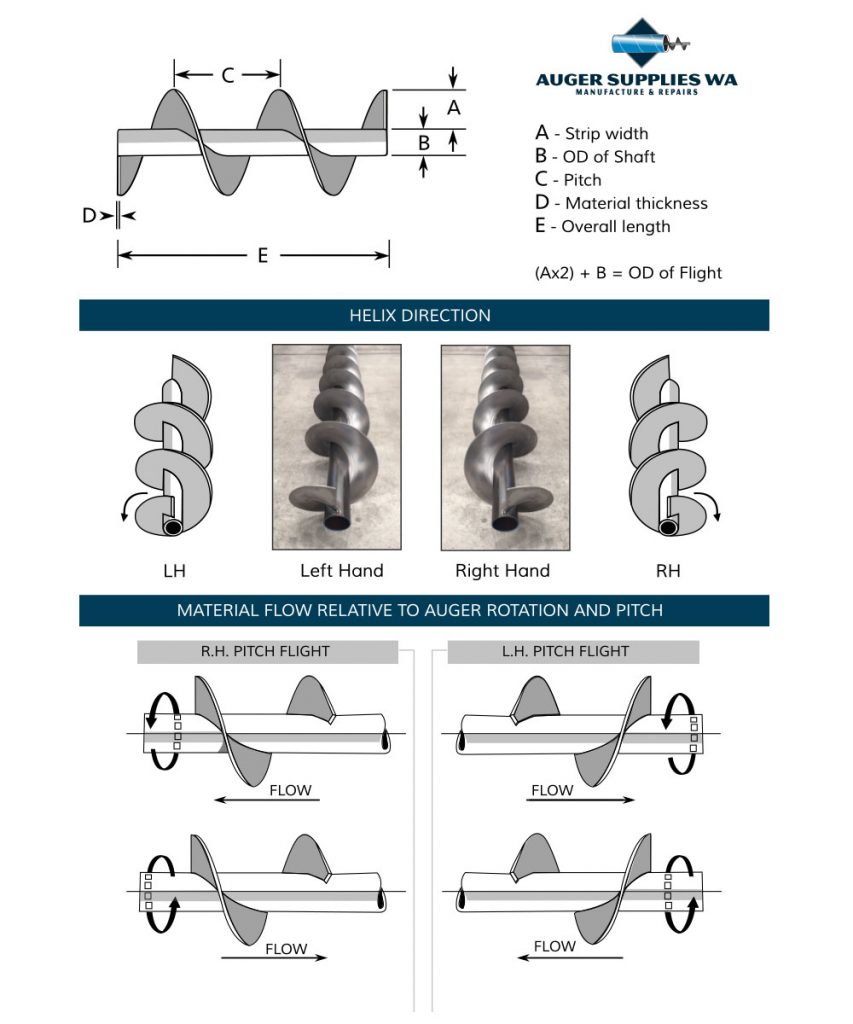
Your auger’s outer diameter directly affects barrel clearance and material movement efficiency. This measurement equals your shaft diameter plus twice the flighting strip width. For example, with a 3-inch shaft and 2-inch wide flighting strip, your OD is approximately 7 inches (3″ + 2″ + 2″). When measuring existing flighting, always take multiple readings across the widest points and average them—especially if the flighting shows wear patterns. If your auger operates inside a barrel, remember the flighting OD should be 1/8″ to 1/4″ smaller than the barrel’s inner diameter to allow for proper clearance and accommodate wear over time.
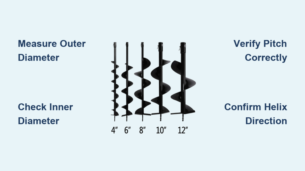
Pro Tip: Don’t confuse nominal barrel size with actual flighting OD. A “6-inch auger” might actually have a 5.75-inch OD due to manufacturing standards. Always measure rather than assume based on marketing terminology.
Inner Diameter (ID): The Shaft Fitment Factor
The inner diameter—often called the bore—must match your shaft size precisely for proper installation and performance. Common ID sizes correspond to standard pipe dimensions: 2″, 2.5″, 3″, and larger Schedule 40 pipe sizes. When measuring, always check the shaft itself rather than the flighting’s inner hole, as worn flighting may have enlarged from use. The flighting’s ID should be slightly larger (by a few thousandths of an inch) than the shaft OD to allow for a proper slip fit during installation.
Critical Warning: Never assume your ID based on nominal pipe size. A standard 3-inch Schedule 40 pipe actually has a 3.068-inch outer diameter. Measure your specific shaft with calipers for accuracy.
Pitch: Why This Measurement Makes or Breaks Performance
Pitch is the single most important—and most commonly mismeasured—auger dimension. It represents the distance from one point on a flight to the exact same point on the next flight, measured along the centerline of the shaft. This measurement directly determines how much material moves per revolution. Standard “square pitch” equals the outer diameter, but pitches can range from 2/3 to 1.5 times the OD depending on application requirements.
Common Mistake Alert: Most people incorrectly measure pitch from outer edge to outer edge, but the true pitch is measured along the shaft centerline. This error causes significant performance issues, as even a 1/2-inch pitch difference can dramatically reduce material movement efficiency.
Helix Direction: Right-Hand vs. Left-Hand Flighting
The helix direction determines material flow direction and is critical for proper system operation. Right-hand (RH) flighting—by far the most common—moves material away from the drive end when rotating clockwise (as viewed from the drive end). Left-hand (LH) flighting moves material toward the drive end. To determine helix direction, imagine your flighting as a bolt: if tightening it (clockwise) would drive the bolt away from you, it’s right-hand.
Expert Note: A length of flighting has only one helix direction regardless of orientation. Turning it around doesn’t change the hand—it only changes which end you’re viewing from. Always verify rotation direction and helix hand together before installation.
Material Thickness: The Hidden Factor in Auger Size
Material thickness affects both durability and precise dimensional calculations. Continuous flighting typically ranges from 3mm to 15mm thick, with outer edge thickness approximately half the original strip thickness due to manufacturing processes. For example, a 5mm strip produces flighting with about 2.5mm outer edge thickness. Segmented flighting maintains consistent thickness from inner to outer edge, commonly 3mm or 5mm.
Why It Matters: Thicker materials resist wear better in abrasive applications but require more power to operate. Measure thickness at multiple points using calipers, as wear often occurs unevenly across the flighting surface.
Measure Auger Flighting in 6 Precision Steps
Step 1: Gather Your Essential Measurement Tools
Before starting, assemble these critical tools:
* Digital calipers for precise ID and OD measurements
* Flexible tape measure for larger outer diameters
* Caliper with depth rod for accurate pitch measurement
* Angle finder for helix angle verification (optional)
* Notepad and camera to document all measurements with photos
Pro Tip: Clean the flighting thoroughly before measuring. Built-up material creates false readings, especially for pitch and thickness measurements on worn sections.
Step 2: Measure Outer Diameter Like a Professional
For unmounted flighting, measure straight across the widest point through the center and take readings at multiple locations. When measuring barrel-mounted flighting, measure the barrel’s inner diameter and subtract 1/8″ to 1/4″ for clearance. If working with flat flighting strip before forming, calculate OD as Shaft Diameter + (2 × Strip Width).
Critical Check: Verify your measurement against the barrel ID if applicable. Flighting OD should be consistently smaller than barrel ID by the clearance amount throughout the entire length.
Step 3: Determine Inner Diameter for Perfect Shaft Fit
Measure your actual shaft diameter with calipers—never assume based on nominal pipe size. The flighting’s inner diameter should be slightly larger (0.005″ to 0.010″) than the shaft OD for a proper slip fit. For worn flighting, measure the unworn section near weld points rather than the center where wear typically concentrates.
Expert Technique: If measuring mounted flighting, remove it from the shaft first. Measuring while installed creates inaccurate readings due to potential shaft deflection and clearance issues.
Step 4: Measure Pitch Correctly (Avoiding the #1 Mistake)
This is where most people go wrong. Find a consistent reference point on the flight (like a weld seam or leading edge), then measure along the shaft centerline to the identical point on the next flight. Take multiple measurements at different locations and average them, especially on worn flighting. For severely worn sections, measure near the shaft where wear is minimal.
Critical Warning: Do NOT measure from outer edge to outer edge—that’s not pitch! This common error leads to mismatched replacement parts that cause material flow problems and excessive vibration.
Step 5: Confirm Helix Hand Direction for Proper Material Flow
Hold the flighting so the spiral moves away from you. If a clockwise rotation would move material away from you, it’s right-hand (standard). If counter-clockwise rotation moves material away, it’s left-hand. Create a simple diagram showing rotation direction and material flow to verify before ordering.
Pro Tip: Mark the helix direction clearly on your measurement documentation. Many suppliers require this specification in writing to prevent installation errors.
Step 6: Document All Specifications Before Ordering
Record these six essential measurements:
1. Outer Diameter (OD): __ inches (with tolerance)
2. Inner Diameter (ID): _ inches (must match shaft size)
3. Pitch: inches (critical for performance)
4. Material Thickness: inches (affects durability)
5. Helix Hand: □ Right-Hand □ Left-Hand (verify with diagram)
6. Total Length: ___ inches (for complete replacement)
Quality Control Step: Verify all measurements three times before submitting to your supplier. Cross-check with existing parts if available, and always provide photos of your measurements in context.
Common Auger Measurement Mistakes and How to Avoid Them
Pitch vs. Outer Edge Distance: The Most Costly Confusion
The single biggest measurement error occurs when technicians measure from outer edge to outer edge instead of along the shaft centerline. This mistake creates flighting that looks right but performs poorly. To avoid this, use a depth rod on your calipers to measure directly along the shaft, placing one point at a reference mark on one flight and the other point at the identical location on the next flight.
Real-World Consequence: A 1/2-inch pitch error on a 6-inch auger can reduce material flow by up to 20%, requiring higher RPMs and more power to move the same amount of material.
Measuring Worn Flighting: How to Get Accurate Readings
Worn flighting presents unique measurement challenges. Focus on unworn sections near weld points or the inner diameter where wear is minimal. Take multiple pitch measurements and calculate the average. For OD measurements, account for wear by measuring the barrel ID if possible, then subtracting standard clearance.
Expert Technique: For severely worn flighting, measure the shaft diameter and original strip width if visible, then calculate the theoretical OD rather than measuring the worn surface directly.
The “Assumption Trap”: Why Standard Sizes Don’t Apply
Never assume measurements based on nominal size labels like “6-inch auger.” These labels often refer to barrel size, not flighting dimensions. Always measure actual components. Standard pipe sizes differ from actual dimensions (a “3-inch pipe” is actually 3.5 inches OD), and flighting dimensions vary by manufacturer.
Critical Reminder: Document all measurements with photos showing your measurement technique. This provides proof if disputes arise with suppliers about incorrect parts.
Troubleshooting Auger Performance Issues from Measurement Errors
Poor Material Flow? Check Your Pitch Measurement First
If your new flighting moves less material than expected, pitch measurement error is the likely culprit. Verify your pitch measurement against the old part—many older augers use less than square pitch (pitch less than OD). Measure multiple pitches on both old and new flighting to identify mismatches.
Quick Fix: For minor pitch mismatches, adjust auger RPM to compensate. However, significant differences require replacement with correctly pitched flighting.
Vibration Problems: How Incorrect Inner Diameter Causes Chaos
Excessive vibration often stems from an inner diameter that’s too large for the shaft, creating play during operation. Check your ID measurement against the shaft OD—there should be a snug slip fit with minimal clearance. Even 0.020″ of excess clearance can cause dangerous vibration at operating speeds.
Prevention Tip: When measuring ID, check for ovality—worn flighting often becomes egg-shaped, requiring more than a single diameter measurement.
Wrong Hand Direction: The Simple Fix for Backward Material Flow
If material flows opposite to expectations, you’ve likely installed flighting with the wrong helix direction. Verify rotation direction at the drive end and match it to the flighting hand. Right-hand flighting requires clockwise rotation (as viewed from drive end) to move material away from the drive.
Immediate Solution: If you discover the error after installation, you may be able to reverse the flighting orientation if your system allows, but this isn’t always possible. Prevention through accurate measurement and documentation is far better than correction.
Measuring auger size correctly prevents costly mistakes that lead to downtime and wasted resources. Focus on the five critical dimensions—OD, ID, pitch, helix hand, and thickness—and follow the precise measurement techniques outlined here. Double-check pitch measurements especially, as this single dimension most often causes performance issues. Document everything thoroughly with photos and precise measurements before ordering replacement parts. If you’re ever uncertain, consult with your supplier using your documented measurements rather than guessing. Taking just 20 extra minutes to measure auger size accurately can save you days of downtime and thousands in replacement costs.